Tutorial for Creating a Parabolic Dome Awning
Stephen M. Hollister,
Copyright 2002
This is a step-by-step tutorial to show you how to make a parabolic
dome-shaped awning using Pilot3D. The overall process is
·
Create a center axis line
·
Create the parabolic cross-section shape of the awning
·
Copy/Rotate the cross-section to create the 180 degree shape
·
Skin or fit surfaces to the rotated curves
·
Develop each piece to get the 2D pattern
Step 1 – After starting Pilot3D enlarge the “Front View” to use the whole
window area. You don’t have to do this, but I prefer working on one large
window at a time, rather than four small, separate windows.
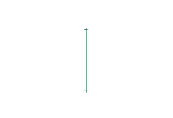
Step 2 – Create a centerline to use as the rotation axis for the awning.
Select the Curve-Add Polyline command. This command allows you to create a line
or polyline by picking the points with the left mouse button and terminating
the shape by picking the right button. In our case here, you want to enter
specific coordinate values for the center axis. This can be done by entering
the (x,y,z) values of the point instead of picking the left mouse button. So,
after selecting this command, type in “0,0,0” (without the quotes), followed by
the enter key. This will put the first point of the center axis at the origin.
Next, enter “0,0,3” to put the second point at 3 feet above the origin. Then
press the right mouse button to terminate the polyline input. You should see
what is shown below.
[Note: if you make any mistakes during this tutorial, you can always use
the Edit-Undo command (which is also the counter-clockwise arrow on the
toolbar).]
Step 3 – Create the parabolic cross-section shape of the awning. You
want to use the Curve-Add Curve command to add a curve, starting at the top of
the center axis. The Add Curve command works like the Add Polyline command in
that you enter curve points with the left mouse button and you terminate the
input using the right mouse button. However, for the first point, you want to
“snap” it to the top of the center axis polyline. This is done by positioning
the cursor near the top edit point of the axis line and pressing the ‘p’ key on
the keyboard (snap to a Point) rather than picking the left mouse
button. After you do this, you want to use the left mouse button to add a few
points to define a nice parabolic shape to the curve, as shown below. Don’t
worry about the straight, vertical piece at the bottom. You will add that in
the next step. Remember to use the right mouse button to terminate the
parabolic curve shape. Also, don’t worry about getting the exact shape that you
want right now. You can always go back and use the Edit-Move Point command to
change the shape of the curve after it has been created.
Step 4 – To add the short, straight vertical piece at the bottom, you
want to use the Curve-Add Polyline command. Remember to snap the first point of
the polyline to the bottom of the parabolic shape using the ‘p’ key on the
keyboard.
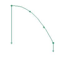
Step 5 – Use the Edit-Move Point command to change the shape of the
cross-section curves until you get the shape that you want – something like the
picture shown below. If you move and separate the common point between the
parabolic part and the vertical straight piece, you can use the Edit-Merge Pnt
To Pnt command to make sure that the two pieces remained attached.
[Note: Pilot3D has a whole set of fine-tune shaping and smoothing
commands for curves and surfaces, but they will not be discussed in this
tutorial.]
Step 6 – Now that the center axis line and the parabolic cross-section
shapes have been created, it’s time to make copies of the cross-section curve
and rotate them about the center axis. To make the job easier, you need to
first tell the program what you want to use for the central rotation axis. This
is done with the Modify-Rotate Entity/Group-Pick Rotate Axis 2 command. This
command lets you pick two points to specify a rotation axis. After selecting this command, use the ‘p’
key to snap or pick the bottom point of the center axis polyline. Then use the
‘p’ key again to snap or pick the top point of the center axis. You will
immediately see a dialog box like the one below that shows you the two points
that you picked for the center axis – (0,0,0) and (0,0,3), which are the two
coordinate values you originally used to create the center polyline. You should
also go to the “Rotation Angle” field and enter 15 for the rotation angle,
since we will be creating awning surface panels that cover 15 degrees of the
180 degree half-circle shape of the awning.
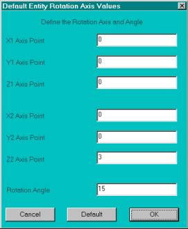
Once you have entered the 15 degree rotation angle, pick the OK button.
Note that nothing happens yet, since this just sets up the default
rotation axis.
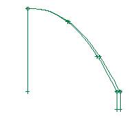
Step 7 – Select the Modify-Rotate Entity/Group-Copy Rotate by Axis
+Angle command and then pick the parabolic curve. You will see the same dialog
box as shown above (already filled in), so just pick the OK button. This
command will create a copy of the first parabolic curve and rotate it by 15
degrees around the center rotation axis. Since the bottom vertical piece is a
separate entity, you need to pick that one separately to create a rotated copy.
[Note: Pilot3D uses something
called a default command technique. This means that when you select a command
to use (the Copy Rotate command in this case), you don’t have to re-select it
to use it again. This command will stay current until you select another
command. The current command is shown in a box in the lower right status line
of the main program window.]
This means that you can keep using the Copy Rotate command for each
curve, one right after another. After using the Copy Rotate command for each
part of the cross-section curve, you should see something like what is shown
below.
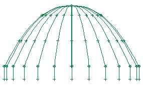
Step 8 – Since the default rotation angle is 15 degrees, you need to
keep using the Copy Rotate command on each of the new curves that are
created (not the original cross-section curves). Keep using the Copy Rotate
command until you have added 12 new parabolic curve shapes and 12 new vertical
pieces, as shown below.
Step 9 – To verify the shape, you can select the “3D” command on the
toolbar as, shown below. Then you can use the rotate commands (the ‘Z’ buttons
with the clockwise and counter-clockwise arrows) to better view the shape that
you have created. The “UP” and “DN” (down) buttons allow you to tilt the shape
up or down while you rotate it back and forth.
![]()
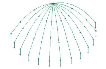
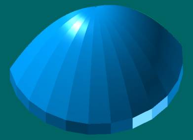
After rotating and tilting the shape, you should see something like what
is shown below. This shows the 3D
wireframe shape of the awning, which is ready for skinning with surfaces.
Remember, our first goal is to define all of the seam or structure lines with
curves, which we have just done.
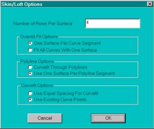
Step 10 – To fit the area between each set of two consecutive curves
with a surface, we need to use the Create 3D-Skin/Loft command. After selecting this command, you need to
pick (left mouse button) each curve (in sequence order) to tell the program
which curves to skin or fit with a surface. In our case here, we will be
skinning or fitting a surface between each consecutive set of cross-section
curves. In other words, we want to fit surfaces to each of the 12 separate
sections of the awning. As you pick
each curve, you need to pick the curves near the same ends. This tells the
program how to connect the two curves with the surface. [Remember that what is
obvious to a human is not so obvious to a computer program!] Once you have
picked two consecutive curves, pick the right mouse button to show the
dialog box below. For the parabolic curve part, you want to make sure that the
“Use Existing Curve Points” option is picked. This is not required, but it
makes a better fit for this example.
Next, pick the OK button to create the surface.
[Note: This is a powerful command that allows you to fit many curves
with multiple surfaces at the same time. However, we will not take the time
here to go into the details.]
Step 11 – Keep using the Skin/Loft command to create the rest of the
surfaces (12 parabolic pieces and 12 rectangular pieces). Remember that you do
not have to keep selecting the Skin/Loft command, since the program made it the
current/default command as shown in the lower right box on the screen. You just
keep picking the two consecutive curves and then picking the right mouse button
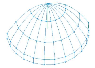
to bring up the dialog box. Once done,
you should see something like what is shown below in the3D view. The curves
have been replaced by the surfaces. [The curves are still there, but they are
turned off.]
Below is the same view in the View-Render View option.
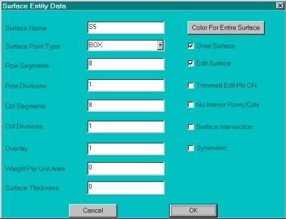
If you want to change the default colors of a surface, use the right
mouse button and click on the surface (somewhere other than along a common edge
between two surfaces). This will display the attribute/option box for the
surface, as shown below. Notice that one of the options is a color choice
option that you can use to set the color of the surface.
Below is what the awning looks like when every other surface has been
changed to orange.

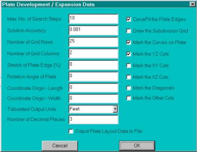
Step 12 – Now you can unwrap or layout any surface that you want using
the Develop-Develop Plate option. After selecting this option and picking a
surface, you should see the dialog box shown below. It contains many options,
but for now, you can accept the default options and just pick the OK button.
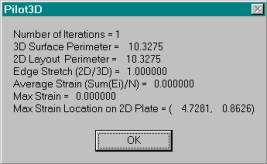
After the calculations are done, you will see a dialog box like the one
shown below. Pilot3D uses a finite
element analysis technique to flatten out the 3D shape into its 2D pattern. In
this case, the shapes are simple with no complex curvatures and no strains in
the material.
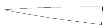
After you pick the OK button, you should see the following pattern for
one of the parabolic surface sections.
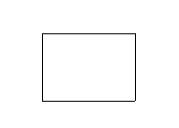
This is the 2D pattern for the rectangular section.
Of course, we didn’t need to model the entire 180 degree awning shape if
all we wanted were the two patterns above, since all of the patterns are the
same. However, the complete model is
nice for viewing and marketing purposes.
Step 13 – To get the full-size plotted patterns, just use the print
command. [You may need to go to the Options-Mod/Doc Definition dialog box to
set the values to a user-selected scale factor and set the scale to 1 foot
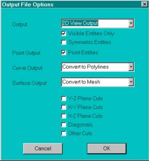
equals 1 foot.] To send the patterns to
a CNC machine compatible format, you need to display the pattern on the screen
and then select the File-Data File Output-DXF Output command. The following
dialog box will appear. The only value that you have to change is the Output
field from 3D output to 2D View Output. Then pick the OK button.
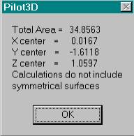
Step 14 – If you want to calculate the amount of material you need,
select the Calc-Surface/Group Area-3D Area command. When you pick a surface,
the 3D area and center will be calculated and displayed as shown below. To get
the total area of the awning, you will have to multiply the sum of the areas of
the two-surface section by 12.
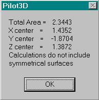
You can also get the total area by first using the Edit-Group
Entities-All Surfaces command first. Then, when you use the Area 3D command and
pick any surface, the command will be applied to the whole set of surfaces and
the results will be displayed as shown below. [Most commands work for one
entity if the picked entity is not part of the current group. However, if the
picked entity is part of the current group, many commands apply to the entire
group of entities.]
That’s it! This process is not completely automatic, but with a little
bit of practice you will be making 2D patterns for some complicated, creative
shapes.