How Do You Create 3D Geometry?
[You should read the tutorials about the basic geometric
entities (points, lines, polylines, curves, combo curves, and surfaces) before
reading this tutorial. This tutorial talks about using those basic entities to
create complex 3D shapes.]
Pilot3D gives you many ways to create surfaces and piece them together
to get complex 3D shapes. Some ways are easier than others, so it helps to have
an overview of the different techniques. This tutorial will give you a feel for
the process and point you to more detailed tutorials.
Exact or General Shape
The first thing to determine is whether the 3D model you want to design
has exact dimensions that you want to match up. Many people want to recreate
(as closely as possible) some sort of 3D object. It might be a car or a
building. For this, you might want to start with a sketch that shows the basic
dimensions and positions.
To do these measurements, you need to know something about [X,Y,Z]
coordinates. You need to define your object relative to some sort of measuring
location or origin. You need to change measurements of length, width, and
height into [X,Y,Z] positions. For example, if you want to define a house, you
need to define a starting point (origin) for measuring everything, which might
be the southwest corner of the lot. This is the point you need to define all
[X,Y,Z] measurement points. Then you could say that the positive X-direction
goes to the east, the positive-Y direction goes north, and the positive-Z
direction goes straight up. All of the dimensions of the house could be changed
into [X,Y,Z] values measured from the corner of the lot.
A fast way to start in Pilot3D is to define point entities for each
critical point on the house; each house corner, each window and door corner,
each roof corner, even points that define the key points on the chimney. You
can use the Point-Add Point command and then right-click on the point to pop up
a dialog box to set the [X,Y,Z] value of that point. As you can see, this is
much more difficult than creating a 3D object that doesn’t have exact
measurements to match up.
Once you have all of the critical points defined, you can snap lines or
polylines between the points. This is done with the basic Curve-Add Polyline
command, but instead of left-clicking the definition of each point, you
position the cursor near one of the previously defined points and press the ‘p’
key on the keyboard. This tells the program to snap (use) the position of the
edit point that is closest to the cursor location.
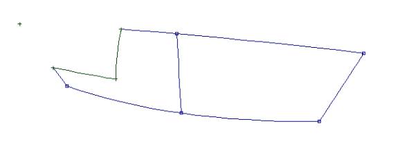
Going from polylines and curves to surfaces
OK, but there has to be some method to all of this. The goal is to
create lines or edges that you can connect (skin/loft) with a surface. Think of
a simple rectangular side of a house with 4 points that define the corners. You
could snap a line between the top 2 points and snap a separate line between the
bottom 2 points. Then you can use the Create3D-Skin/Loft command to stretch a
surface between the two lines.
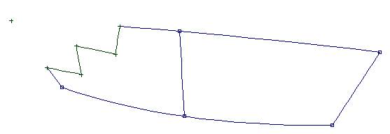
This is a common method for creating 3D objects with specific
measurements; define points, snap lines or curves between the points, and then
skin/loft surfaces between the lines or curves. [Some designers skip points and
go straight to lines and curves to speed up the process.] If the lines or curves
define the boundaries of the object, you will end up with a complete 3D NURB
model when you are done with the skinning/lofting process.
As you will see, converting lines, polylines, and curves to surfaces is
a common technique for creating NURB surfaces.
Here is a list of these commands, available under the Create 3D
pull-down menu.
Create3D – Extrude Surface – Extrude Straight
This command takes a line, polyline, curve, or combo curve and creates a
surface by extending the curve straight (into the screen direction) based on
the view displayed. For example, you could take one of the standard 2D airfoil
shapes and create a full 3D airfoil by extending the 2D shape for 3 meters.
Note that for any of these extrude commands, when it is applied to a
polyline or combo curve, many surfaces could be created. For example, if you
extrude a 2D square, it becomes a 3D box made up of 4 separate surfaces. The
added bonus, which is VERY IMPORTANT for 3D modeling, is that these surfaces
are “bonded” or connected. This means that you can edit the extruded shape and
the surfaces will not separate. Very few (if any) other CAD programs offer this
capability. Surfaces can also be un-bonded or bonded edges can be changed to
smooth edges – combining two surfaces into one surface (or vice-versa), kind of
like the “knuckle” command for curves. See the tutorial on geometric
relationships for more details.
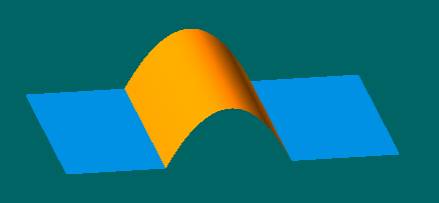
This picture shows a straight-extruded combo curve consisting of two
straight lines connected with a curve.
Pilot3D creates three NURB surfaces and bonds the common edges between
the flat and curved surfaces. This means that you can edit the surface edges
without having the surfaces split apart.
[Note: bonded edges have the added bonus of being exact, “watertight” connections
between surfaces. This is important when you need to transfer the surfaces to
solid modelers.]
Create3D – Extrude Surface – Extrude to a Point
This command creates a 3D shape that starts as a 2D shape and disappears
down to a point – kind of like an arbitrary cone, except that the shape is
whatever you want.
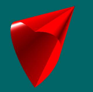
This picture shows two surfaces created by extruding a heart-shaped
combo curve to a point. Combo curves
are very powerful when combined with the extrusion, shelling, and skinning commands.
Create3D – Extrude Surface – Extrude Rotate
This command takes a 2D shape and rotates it about an axis (that you
define) to create a 3D shape. Think of a lathe pattern that is used to cut out
a circular object, like the leg of a table. Note that the rotation angle to use
does not have to be 360 degrees, a full circle.
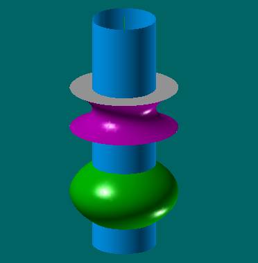
This collection of surfaces was created in one step using the
Extrude-Rotate command on a single combo curve consisting of both straight and
curved sections. This shape was created in about a minute. The surfaces are
bonded together so that you can edit the shape without having the surfaces come
apart. Since they are separate surfaces, they can have their own colors.
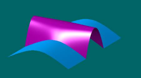
Create3D – Sweep Surface – Sweep Along 1 Curve
This command extrudes a 2D shape, but follows a curve (that you define),
rather than a straight line. This is much more powerful than a straight line
extrusion.
These surfaces were created by sweeping a combo curve along on curved
path. If you look closely in the center opening, you will see the start of the
sweep path. As with the other commands, these surfaces are bonded and can be
edited without having the surfaces separate.
Create3D – Sweep Surface – Sweep Along 2 Curves
This command allows you to create a 3D surface by moving a 2D
(cross-section) shape between 2 edge curves. This is more complicated, but
quite powerful.
This shows surfaces that were created by sweeping a combo curve along
two paths defined at the ends of the straight curve segments. Some programs
call this a two-rail sweep. Once again, the surfaces are bonded.
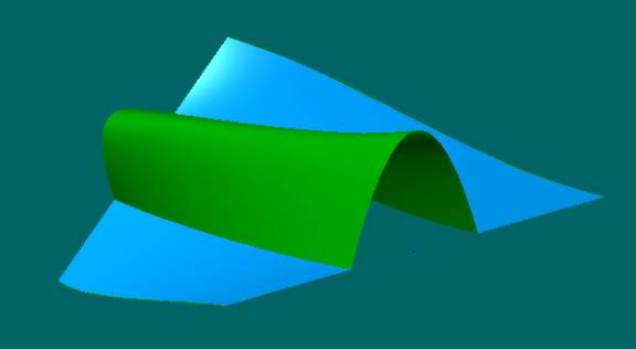
Create3D – Skin/Loft Surface
This is a very powerful command that creates a surface between two or
more lines, polylines, or combo curves. The fastest way to create 3D surfaces
is to use this command between two lines or curves. If you have a series of
cross-section curves of a more complicated surface, this command allows you to
fit a 3D NURB surface that matches (passes through) all of the cross-section
curves. If the “curves” are really polylines or combo curves, and if all of the
polylines or combo curves have the same number of sections, then this command
will fit multiple surfaces between the polylines.
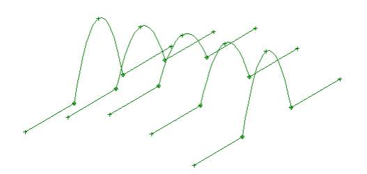
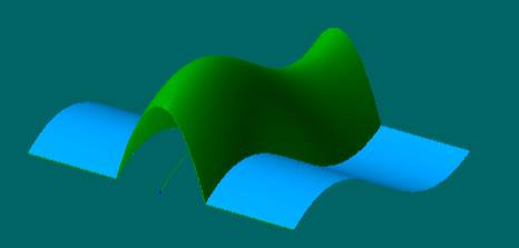
This command fits one or more surfaces to a set of cross-section curves.
In this case, the curves are combo curves and all of them have the same number
of curved and flat sections. The Skin/Loft command will create multiple (3 in
this case) surface that fit each section.
Pilot3D figures finds the three different sections of the curves and
uses those sections to create different surfaces. Three surfaces were created
in the example above and the surfaces were bonded to make further editing
easier.
Direct 3D Solids
There are also commands that can give you (without starting with curves)
basic 3D shapes. They are listed in the Create3D pull-down menu and below. Each
of these shapes can be defined as hollow in the middle.
Triangle Solid – the triangle can change shape and twist angle from one
end to the other.
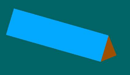
The triangle solid can be closed and bonded completely with NURB
surfaces. The triangle can be any different size on the front and back.
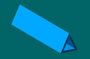
All solids can be defined with any thickness, like a pipe. This picture
shows a triangle with all surfaces (inside and out) defined and bonded
together. You can edit the shape without having the surfaces separate.
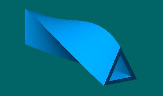
You can even put a twist into any of the 3D objects – still all closed
and bonded.
Box Solid – The rectangle can change shape and twist angle from one
end to the other.
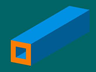
Box solids have the same type of options as the triangle solids. You can
define twist and have the dimensions (width and height) of the two ends be
different.
Cylinder/Cone Solid – The shape can change from a circle to an ellipse
and can be truncated or skewed.
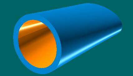
This is a picture of a circle to ellipse cylinder/pipe that was created
with one command. The shape does not
have to be closed. You could define the shape to cover one-quarter of the
closed loop, with the open edges closed off with bonded surfaces.
Sphere/Ellipsoid Solid – This solid can be any angle, from a wedge to a
full, round solid.
This is half an ellipse of a specified thickness with its ends cut off
and capped with surfaces. All surfaces are bonded. This was done with one
command.
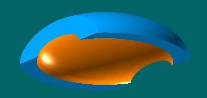
Ruling Line Surfaces
Sometimes, one wants to create surfaces that can be unwrapped from a 3D
shape to a 2D pattern. Pilot3D allows you to create dynamic 3D ruling lines
between any two curves. This is great for cloth patterns, like clothes,
awnings, tents, and kites. You can also use this for curved buildings and boats
made out of sheets, like plywood, aluminum, and steel. You can edit the curves
to get the shape you want and to check the developability of the surface. This
means that you can unwrap the shape without any worry of wrinkles or
creases. Pilot3D can plot the 2D
pattern full size or you can send the pattern to a CNC cutting machine. See the
Develop pull-down menu for the list of commands.
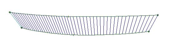
You can have the program calculate and draw ruling lines between any two
curves, as shown above. When you edit (move) any of the edit points, the
program dynamically recalculates and draws the ruling lines. The ruling lines
will be drawn using colors that define the amount of twist in the surface. If
the ruling lines are dark blue, then there is no twist and the surface can be
unwrapped with no kinks or strain. As the colors go from dark blue to green, to
yellow, and then to red, the amount of twist increases. This technique allows
you to dynamically get feedback on developability as you are editing the shape
of the curves. Once you get the ruling
lines just right (like above), then you can fit a NURB surface through the
ruling lines and then unwrap the 3D shape into its 2D pattern, as shown below.
No other program has this dynamic ruling line
calculation capability.
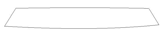
The final 2D pattern can be plotted full size or you can send the
numbers to a DXF file to use with any CNC cutting machine.
Trimming Curves
Sometimes, it might be useful to define sections of a surface to cut off
or cut out. Pilot3D allows you to intersect surfaces or define curves on
surfaces that can be used to trim surfaces. This is a more complicated subject,
so you should see those tutorials (and manual) for details.
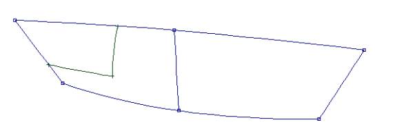
This picture shows a simple NURB surface (with edit points on the
surfaces) and a polyline that is attached to the surface. You can attach
polylines or curves to a surface with the Curve-Add Polyline to Surf and the
Curve-Add Curve to Surf commands. The polyline or curve will stay on the
surface even if you edit just like a regular polyline or curve.
Use the Surf-Trim Curve command to pick the trim curve on the surface
and then pick the part of the surface you wish to trim off. Pilot3D also allows you to edit the shape of
the trim curve after you have trimmed the surface. Most CAD programs require
you to untrim the surface, edit the shape of the curve, and then retrim the
surface.
This shows the same surface after the trim curve has been edited. Again,
this is done without untrimming the surface.
Attaching curves to surfaces to use as trim curves can save a lot of
time with the editing process. In many cases, you can create trimmed shapes
that are difficult or impossible to do with intersecting or extruded surfaces.